Audio Electronics
An electronics course with a focus on audio equiptment analysis and circuit design. Coursework included basic electronic components and theories, passive filtering, transformers, operational amplifiers, equalizers, compressors, microphone preamps, and analog effects including reverb, flanging, and chorusing. All circuit designs were simulated using Circuit Maker.
Projects
-
Lab 1 - Voltage Divison and I/O Impedance
ReportAn introduction to Circuit Maker. We simulated several basic circuits including a voltage divider and became familiar with performing DC and AC circuit analysis.
-
Lab 2 - 1st Order Passive Filters
ReportIn this lab we began working with passive filters. We created several low pass filters and analyzed their frequency response. We learned how to calculate a circuit's transfer function and use that to design other filters.
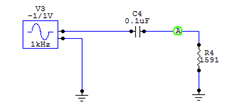
High pass filter circuit designed for a center frequency of 1kHz 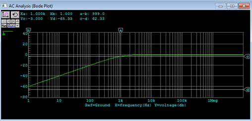
Frequency response of the HPF with Fc = 1kHz visible -
Lab 3 - Shelving Filters and Loudspeaker Crossovers
ReportWe improved on the simple high pass and low pass filter design to create more practical variable shelving filters. Then we applied those shelving filters to design loudspeaker crossovers that split frequencies into high, low, and middle bands to be played with separate drivers.
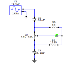
Variable high shelving filter with a break frequency of 6kHz 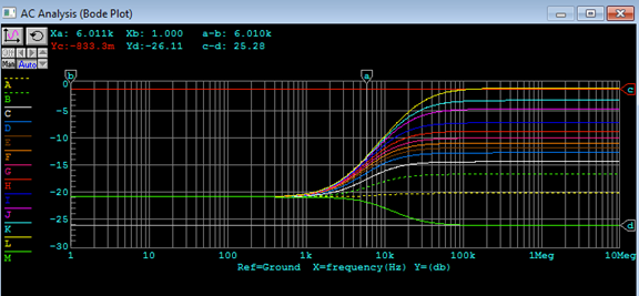
Frequency response of the above filter with potentiometer values set between 1% and 99% 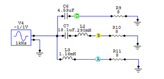
3-Way Loudspeaker crossover circuit with driver diameters at 10" (woofer) and 2.5" (midrange) 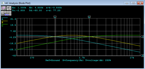
Output voltages shown taken from the 3 outputs of the crossover circuit -
Lab 4 - Transformers
ReportExperimenting with transformers. We created some circuits in Circuit Maker that utilize transformers including a balanaced/unbalanced signal conversion circuit and performed transient analysis to observe voltage changes and phase shifts.
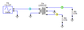
Unbalanced to balanced signal converter using a 1:1 transformer 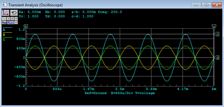
Output voltages with the 1V input in cyan and the two phase shifted 0.5V outputs in green and yellow -
Lab 5 - Op-Amps
ReportUsing operational amplifiers in our circuits to design a practical amplifier for a guitar that fits our required specifications of up to 40dB max gain and a sufficiently wide frequency bandwidth. We also used an op amp as a unity gain buffer to match impedances between the guitar and our amp.
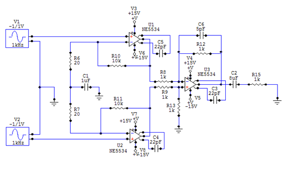
Amplifier circuit with a max gain of 40dB designed for a 6-string electric guitar 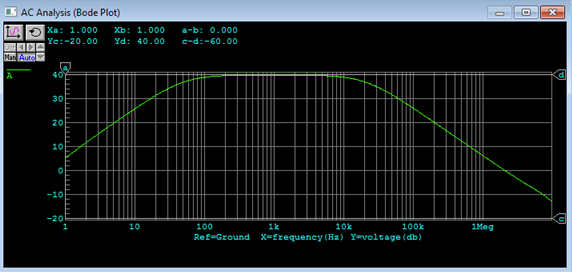
Voltage gain shown to be 40dB in an acceptable frequency range -
Lab 6 - Microphone Pre-Amp Design
ReportWe designed microphone pre-amps; versions both with and without a coupled transformer. Our design specifications included designing for a max gain of 60dB and designing for the highest possible gain while maintaining the upper cutoff frequency of 20kHz. The calculations involved accounting for all parts of these multi-component circuits.
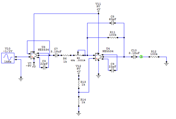
Microphone preamp designed without a coupled transformer 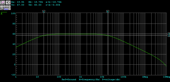
Voltage gain shown to be 60dB in an 18.8kHz bandwidth -
Lab 7 - Filter and Parametric EQ Design
ReportA parametric equalizer is an equalizer that has multiple bands and lots of control over multiple parameters. They are designed to use variable filter types and allow control over the center frequency, amplitude, and Q factor. Our parametric EQ module was designed to control one band with the potential to be cascaded into a full multi-band unit.
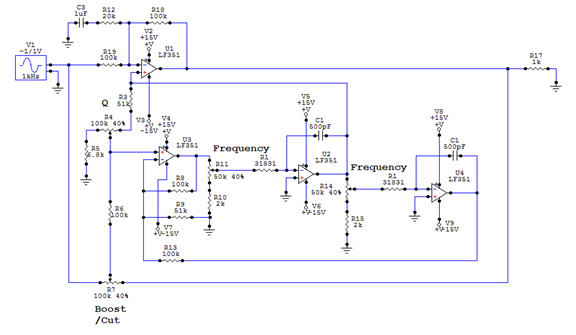
Parametric EQ module with variable potentiometers shown for gain, center frequency, and Q factor 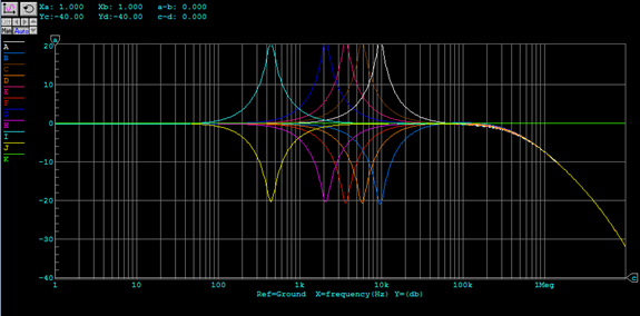
Several different center frequencies shown between 440Hz and 9.6kHz, approximately a 4.5 octave range 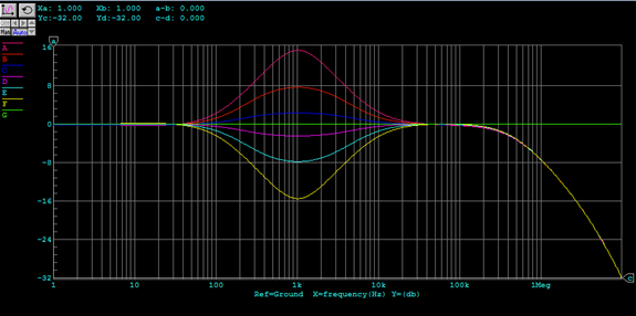
Several different values shown for amplitude on one frequency 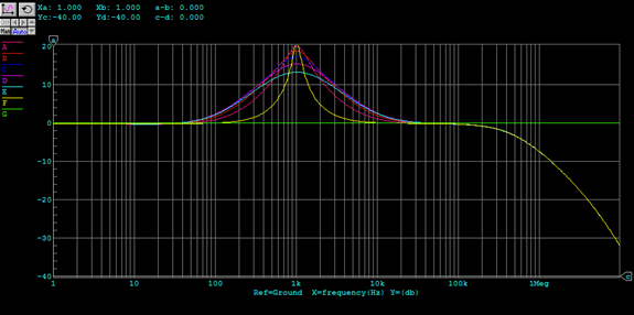
Several different Q values shown on one frequency at max gain -
Final Project - Complete Mixer Design
ReportOur final project combined all of the components we learned throughout the semester. We created and simulated a full mixer console that controls signal flow from microphone input to a summed, balanced output. The stages of this console include a microphone preamp, a rumble filter, a parametric EQ, a 2-band shelving filter, a channel monitor with 2 aux sends, and the final mixer output unit that combines all input channels into a single balanced output.
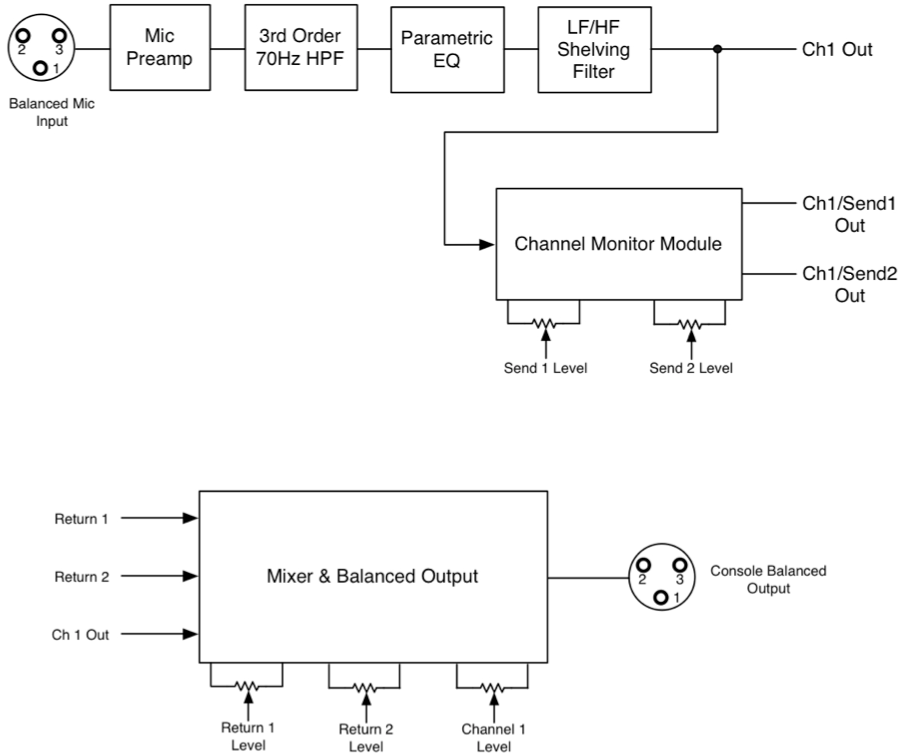
The top-level schematic of the console 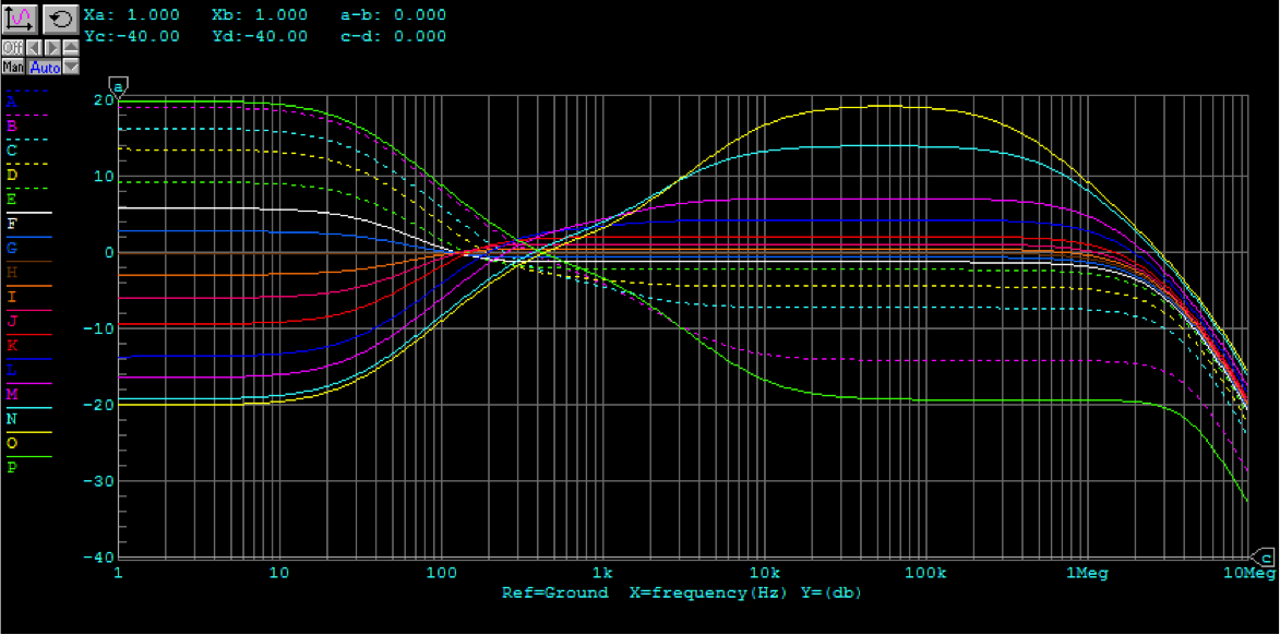
A representation of the various settings available to the shelving filter 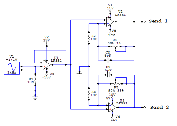
The channel monitor module circuit splits the input signal into 2 new inputs, each with up to 20dB gain control 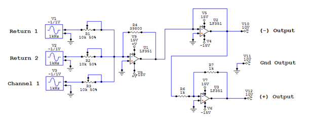
The final mixer circuit sums the dry signal and 2 return signals into a balanced output