PCB Design
PCBs, or printed circuit boards, are metal boards composed of various layers of copper and non-conductive substrates that house and connect electrical circuits. They are found in virtually every electronic device. PCBs are mass produced and can be manufactured with incredibly fine precision. In this course we studied digital audio system designs and architectures and learned how to design a PCB layout from a circuit schematic. Our schematics were created in CircuitMaker and our PCB layouts were done in ExpressPCB.
Projects
-
Transformerless Balanced Mic Preamp
Schematic
PCBA microphone preamp is a circuit designed to boost the low output signal from a microphone to a level high enough to transmit to mixing consoles and recording devices. A balanced preamp means the circuit accepts a balanced signal (two identical signals with opposite polarity, shown as + and -) and also outputs a balanced signal. This circuit uses an initial differential amplifier to perform signal amplification and two operational amplifiers to achieve a balanced output.
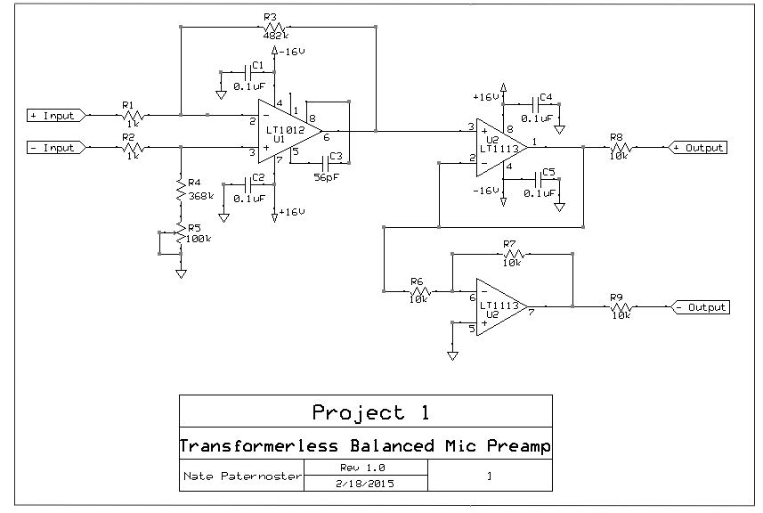
A simple balanced microphone preamp using 2 operational amplifiers 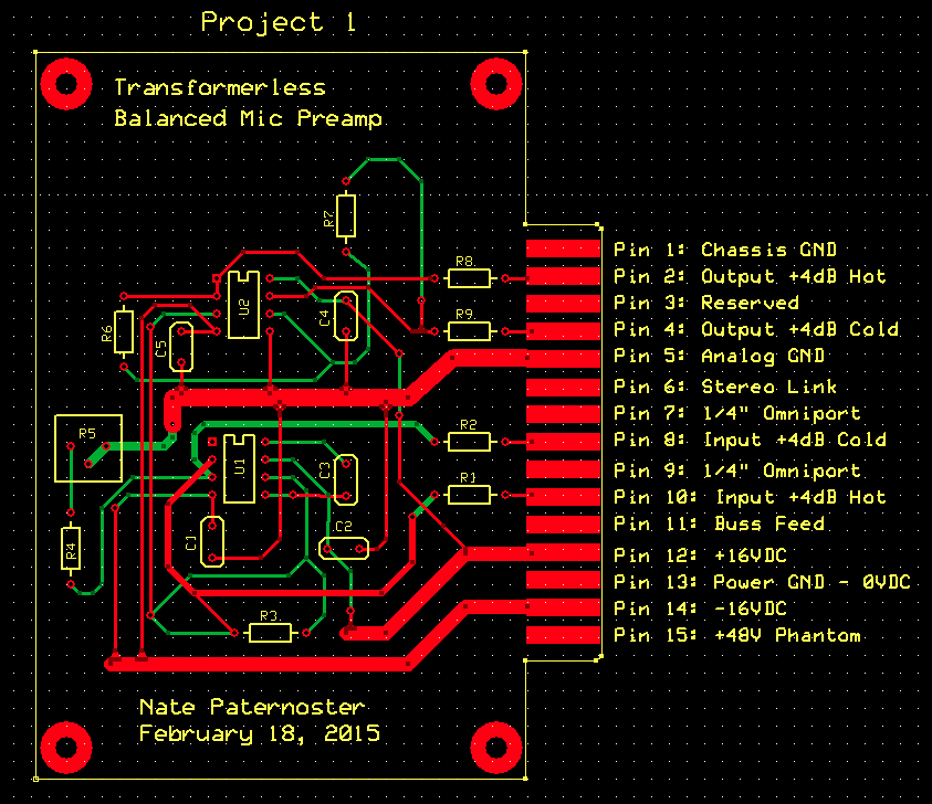
The above circuit realized on a printed circuit board -
High-Performance Balanced Mic Preamp
Schematic
PCBThis mic preamp more than doubles the number of components from the previous circuit to achieve a cleaner output signal. It provides 48V phantom power at the input and makes use of coupling capacitors to remove the introduced DC bias from the rest of the circuit. Decoupling capacitors are also used at the voltage supply terminals to the op-amps to remove AC noise from the DC supply. The first half of the circuit performs most of the voltage amplification on each signal individually while the second stage performs the balanced signal subtraction. The last stage uses 2 additional op-amps to produce a balanced output.
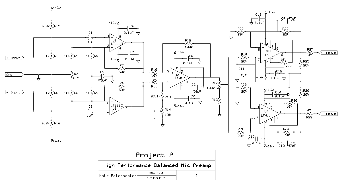
A high performance balanced microphone preamp with several stages 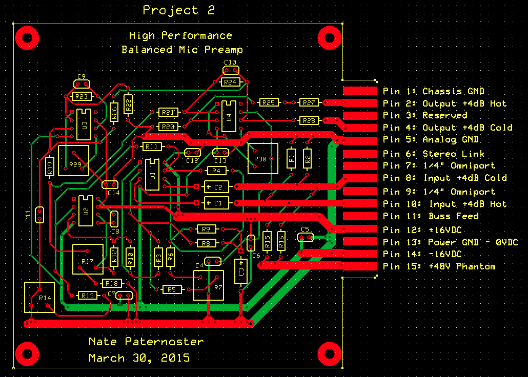
The above circuit realized on a printed circuit board -
Parametric EQ Module
Schematic
PCBAn equalizer (EQ) is a circuit that allows adjustment of the balance between frequency components in a signal. They are widely used in audio recording, editing, and reproduction. A parametric EQ is one that allows the adjustment of every parameter (boost, cut, center frequency, and Q factor). This parametric EQ circuit can be broken into 3 stages. The 1st stage converts the balanced input signal into an unbalanced signal and the 3rd stage converts the unbalanced signal back into a balanced output. The 2nd stage contains the parametric EQ circuit.
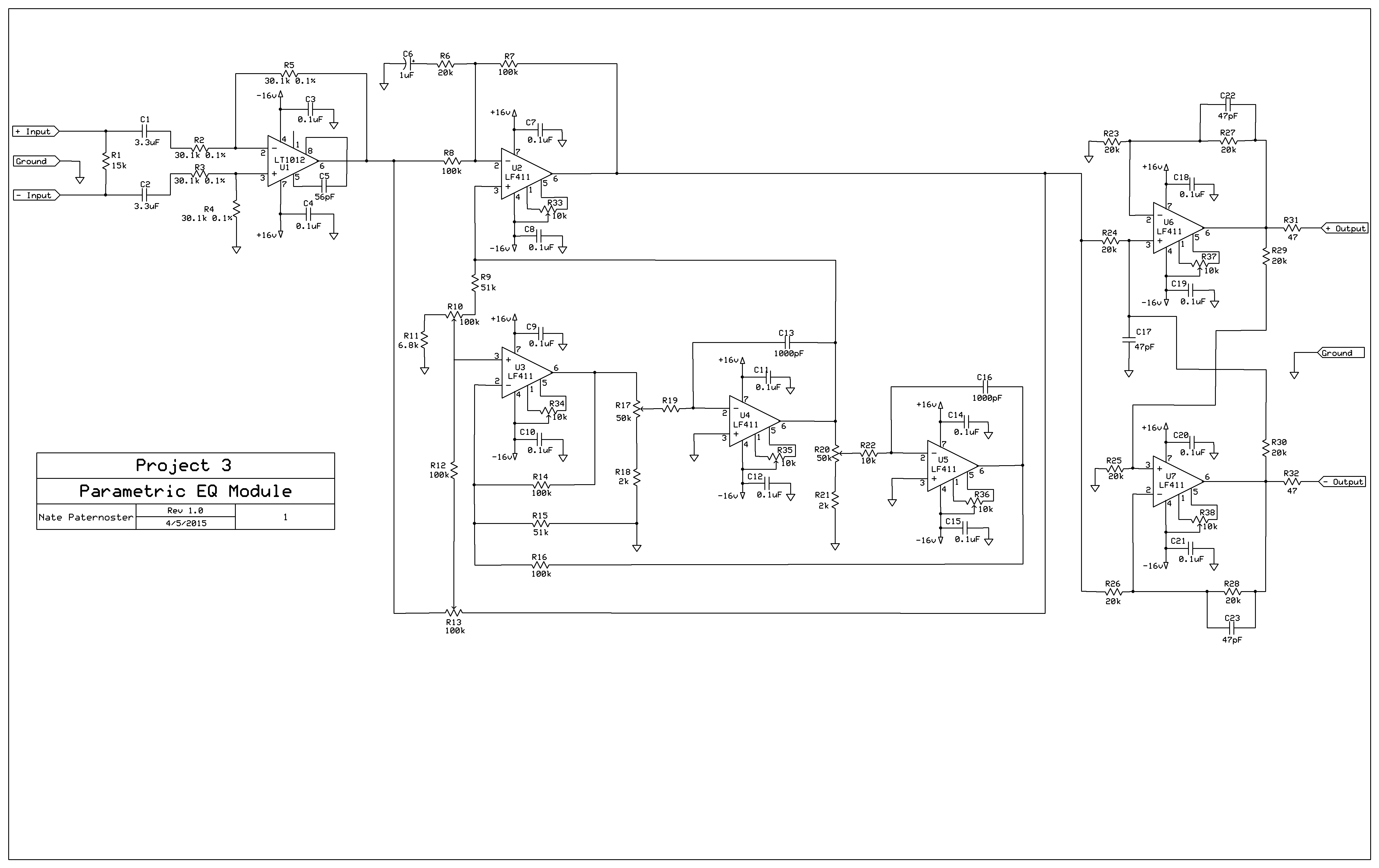
A stereo parametric EQ circuit 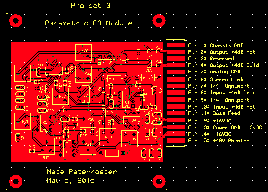
The above circuit realized on a printed circuit board -
Stereo Reverb
Schematic
PCBThis example of an analog stereo reverb circuit performs an audio reverb effect on a balanced, stereo input signal. It makes use of the MN3011 delay chip and an LM555 timer chip. The MN3011 delay chip provides 6 independent outputs for 1 input signal, those outputs all being delayed by different amounts of time. 3 of the outputs are summed together and mixed with the (+) input signal and the other 3 with the (-) signal. This produces the characteristic echo of the reverb effect.
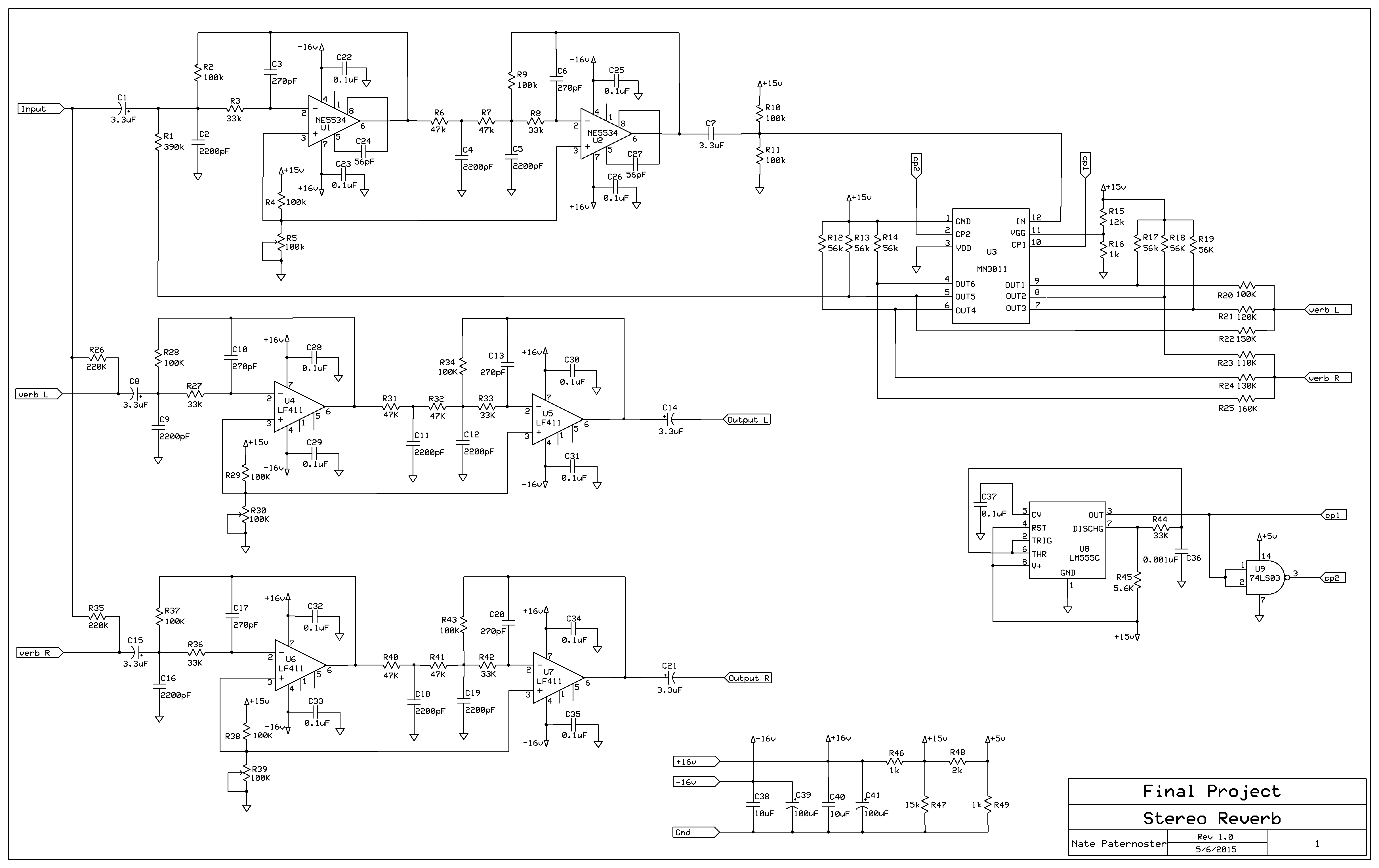
A stereo reverb circuit making use of the MN3011 chip 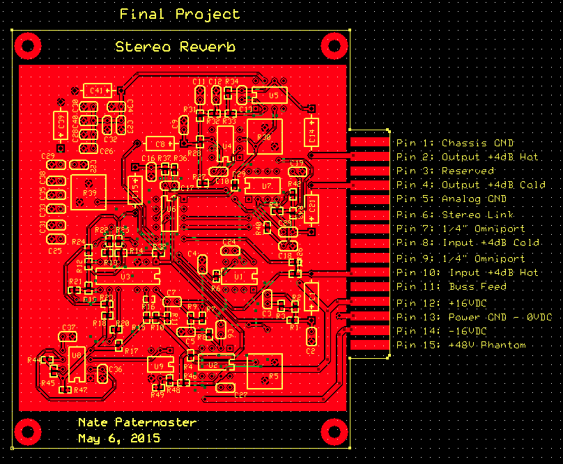
The above circuit realized on a printed circuit board